Article originally featured in Trenchless Technology
Nuts and Bolts of Guidance
By Jed Sheckler and Michael Rybak
Maximize HDD Accuracy with Combined Guidance Technologies
Horizontal Directional Drilling (HDD) continues to experience rapid growth with proven effectiveness across a diverse range of installations. HDD is an essential part of the expansion and replacement of our data, electrical, water, energy, and waste networks. Exploring the practical limits to the method’s accuracy has been a popular topic of discussion within the trenchless community.
In a year when both the NASTT and European Drilling Contractor’s Association are updating their best practices and guidelines, it is important to have a clear understanding of the role of guidance systems in maximizing the accuracy of the HDD process.
Guidance Overview
There are a variety of methods of guiding an HDD pilot bore. While details may differ depending on the manufacturer’s approach, a complete downhole HDD guidance system must provide the following capabilities.
Steering puts the Directional in HDD. The drilling assembly is fitted with an offset bit, sub, or motor. An accelerometer in the steering tool informs the driller of the current inclination and roll-angle. Orienting the offset and pushing (sliding) the drillstring without rotation provides directional control of the borehole.
Surveying calculates the location of the pilot bore as it progresses. Surveys are taken at discrete positions (typically when making a drill rod connection) when there is no fluid flow, and the sensors are most stable. Downhole HDD survey tools are fitted with accelerometers measuring inclination, paired with magnetic or gyroscopic sensors measuring borehole azimuth. Inclination and azimuth readings are combined with Measured Depth (MD – total drill pipe length) to calculate the current borehole position typically using the Minimum Curvature calculation method. This calculation is made relative to an origin tie point (typically the bore Entry Point) with each new survey point tied to the previous, forming a continuous path back to the origin tie point at surface (Figure 1).
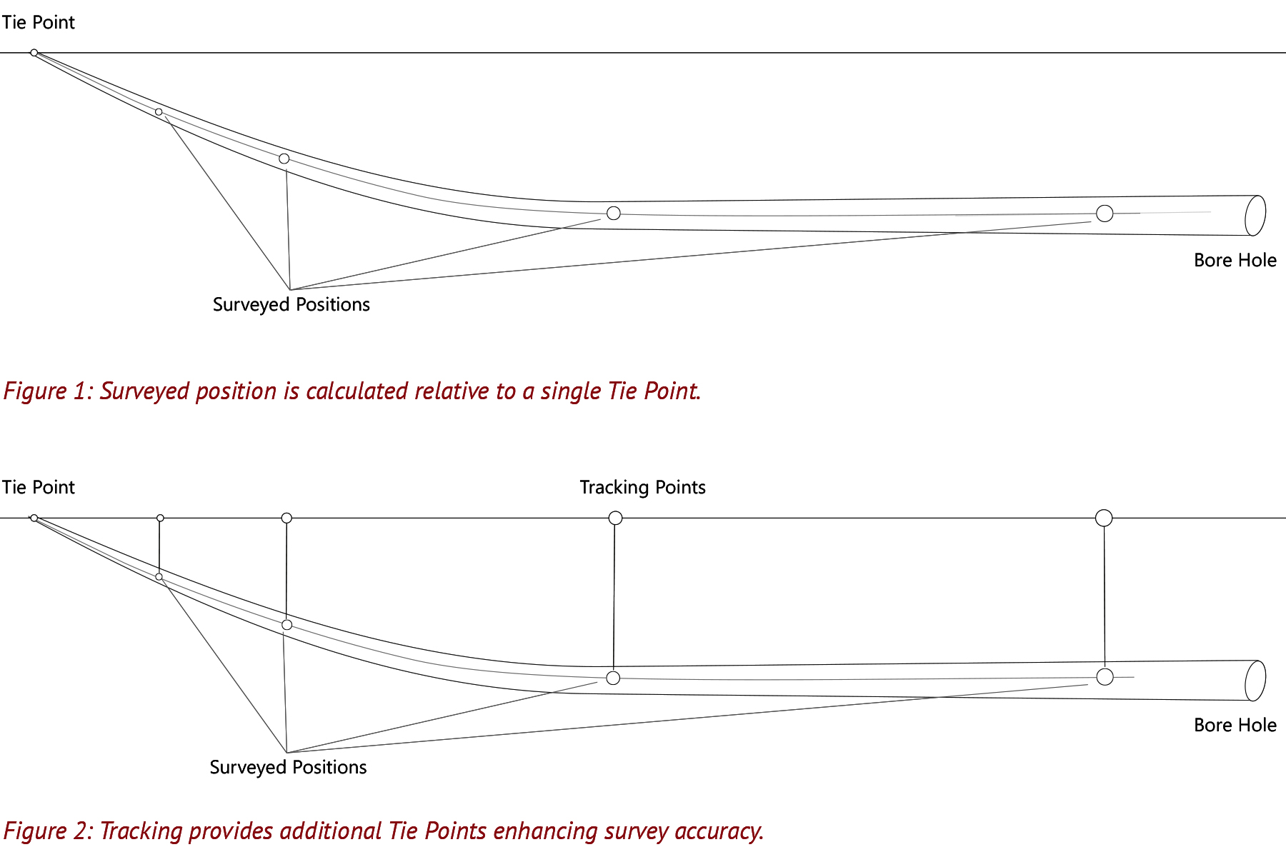
Tracking verifies the calculated survey position by making direct measurements relative to external reference points. A tracking source (ParaTrack2 electrical cable, Beacon Tracker System, Microcoil, etc.) is placed at a known location on surface or run through an adjacent, completed conduit. The source is periodically electrified and emits an electro-magnetic signal sensed by the magnetometers in the survey tool. The signal is emitted from a known location, at a known intensity, at a known frequency, providing a series of additional tie points, greatly increasing the accuracy of the surveyed position (Figure 2).
Sources of Error
While technological advancements (including the development of various brands of gyro tools) have greatly improved the quality of HDD surveys, it is important to understand the types of error that may act independently or in combination to influence the accuracy of an HDD guidance system.
Random errors are unpredictable and may appear as though no one sample repeats (low precision). However the impact of random errors are minimized by increasing the sample size and averaging. Adequate sampling makes it possible to obtain accurate answers from highly random data sets.
Systematic errors are consistent and reproducible, imparting a bias to the data. When drilling on survey data alone, without the benefit of additional tie points from an external tracking source, systematic error will typically become the main source of positional uncertainty over long-distances (>1,000ft).
Gross errors are, in short, typically caused by human error. Gross errors can be especially difficult to detect as they cannot be modeled or effectively planned for. Gross errors include input errors (moving a decimal point), transciption errors (flipping a sign, transposing a digit), or operational errors due to a lack of training, etc.
Ellipse of Uncertainty
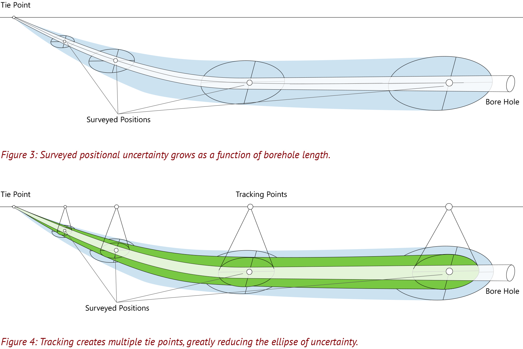
While all three types of error may act independently or in combination, it is widely accepted that the majority of borehole surveying uncertainty is due to systematic errors in the surveying system. Small errors in inclination, azimuth, and depth systematically accumulate. This accumulation forms an ellipse of uncertainty regarding the true position of an inclined borehole that grows as a function of drilled length (Figure 3).
Maximum Accuracy. Minimum Risk.
The positional uncertainty that results when a pilot bore is guided from a single tie point presents a risk that all parties must be aware of when considering the available technology. A guidance system combining a precision survey (gyro or magnetic) with secondary tracking (ParaTrack2 electrical cable, Beacon Tracker System, Microcoil, etc.) that identifies and corrects for any induced error results in the highest achievable accuracy for HDD (Figure 4).
Modern HDD job sites fuse the latest technological advancements with the realities of getting product in the ground. Above all is the need to identify potential sources of risk that could slow progress, result in an accidental strike, or worse yet, cause the project to fail entirely. A clear understanding of the capabilities and limitations of available guidance technology ensures constructable designs with tolerances that can be realistically followed, maximizing the chances of a successful outcome.
Jed Sheckler is the Director of Marketing at Vector Magnetics. Michael Rybak is U.S. Services Manager at INROCK.